
You can eliminate manual transfer errors in hot-dip galvanizing. Implement a Fully Automatic Transfer Unit. This unit automates material movement between furnaces, baths, and cooling equipment. You no longer depend on manual handling during these critical steps. These errors often lead to uneven coating and rework. The unit ensures precise positioning and timing. Manual transfer errors reduce output and increase costs. This solution addresses both problems. This post explains common causes of manual transfer errors. You will see how it prevents them. Benefits include consistent quality and safer operations. You will also learn how to adopt one for your plant. You can trust this automation. Keep reading to understand the solution fully.
Key Takeaways
- · The Automatic Transfer Unit replaces manual material movement with automated conveyors and sensors. This action eliminates timing and positioning errors.
- · Consistent coating thickness and higher output come from precise automated control. The system never tires or makes mistakes.
- · The unit captures waste heat from furnaces to heat solutions. This reduces fuel costs and energy bills.
- · Operators stay away from hot furnaces and toxic baths. The system improves safety and reduces injury risks.
Manual Transfer Errors in Galvanizing
Common Causes on the Line
You see manual transfer errors most often during the movement of steel between heating furnaces, galvanizing baths, and cooling equipment. An operator uses hooks, cranes, or manual carts to move hot materials. This work creates several failure points. Inconsistent timing stands out as a major cause. A load may arrive at the bath too early or too late. The temperature profile then changes. The coating thickness varies as a result.
Operator fatigue also plays a large role. Repetitive work slows reaction times. You may see misaligned hooks, dropped loads, or late transfers. These mistakes can trigger unplanned shutdowns. Manual handling delays create unpredictable cycle times. The furnace sits idle and wastes energy. Each manual intervention compounds the problem.
| Contributing Factor | Direct Consequence | Example of Material Handling Error |
| Operator fatigue | Slowed reaction times after repetitive work | Misaligned hooks, dropped loads, late transfers that trigger unplanned shutdowns (costing $1.2M–$3.6M per incident) |
| Inconsistent timing | Process synchronization gaps (load arriving too early/late) | Temperature profile changes, coating thickness variation, rejects |
| Manual handling delays | Unpredictable cycle times | Delays that idle furnace and waste energy, compounding every manual intervention |
Workforce turnover adds another layer of risk. New operators make manual tagging errors. They miss steps, place tags inconsistently, or write illegible identification. These tagging errors force material reprocessing and production pauses. You also lose traceability. That loss directly contributes to downtime and rework.
Impact on Quality and Cost
Uneven coating is the most visible quality problem. When timing or positioning goes wrong, the zinc layer varies across the steel surface. You then must rework or scrap the part. Both outcomes raise your cost per unit. Safety incidents also rise with manual handling of hot materials. An operator who drops a load or touches a hot surface faces serious injury.
Reduced throughput ties all these problems together. Every late transfer, every misaligned hook, and every tagging error slows the line. The furnace and bath sit idle during these delays. Your plant loses production capacity. An Automatic Transfer Unit removes these manual steps. It replaces them with consistent, automated movement. That change directly addresses the root causes you just read about.
How an Automatic Transfer Unit Prevents Errors
Core Components and Control System
An Automatic Transfer Unit replaces manual handling with a coordinated system of conveyor belts, rollers, sensors, and control hardware. Each component plays a specific role. Conveyor belts move material from one stage to the next. Rollers support and guide the load. Sensors track position, speed, and orientation in real time. The control system ties everything together.
Programmable logic controllers (PLCs) regulate speed, direction, and timing. They operate according to predefined parameters or live sensor input. This allows the conveyor to adjust its movement dynamically. Variable frequency drives (VFDs) and smart motors further refine material flow rates. They support dynamic changes in throughput. A compact speed controller, such as the US-51, adjusts voltage output to the drive motor. A rotary dial allows smooth speed adjustment from low to high. You gain full control over conveyor throughput.
The system responds to load and production pace. Sensors feed real-time data back to the PLC. The PLC then adjusts motor speed or stops the belt as needed. This closed-loop approach removes the guesswork that causes manual timing errors.
Automated Positioning and Cooling
Precise positioning starts before the cooling stage. Magnetic rollers sit before and after the air ring. The first track roller after the air ring is magnetic. These rollers ensure the workpiece does not shift, interfere with the air ring, or deviate after passing through it. The material stays smoothly driven to the next process.
A photoelectric switch positions the limiting part. It controls the material bar circulation mechanism. The mechanism stops when the limiting part sits directly below the switch. This enables precise feeding and avoids large deviations.
| Mechanism | Location/Trigger | Function in Eliminating Misalignment |
| Magnetic rollers | Before and after the air ring (first track roller after air ring is magnetic) | Ensure the workpiece does not shift, interfere with the air ring, or deviate after passing through it; keep it smoothly driven to the next process |
| Photoelectric switch | Positions the limiting part | Avoids large deviations by controlling the material bar circulation mechanism to stop when the limiting part is directly below the switch, enabling precise feeding |
Automated positioning also improves coating uniformity. Controlled withdrawal mechanisms ensure even removal of excess molten zinc during the drainage phase. This prevents coating irregularities such as runs, drips, and thickness variations. These defects typically arise during cooling and solidification. Strip steering systems with centering rolls, edge sensors, and closed-loop controls maintain stable, centered strip travel through the cooling zone. This prevents asymmetric coating from air knives. You avoid overcoating on one edge and undercoating on the other. Uniform zinc distribution is preserved throughout cooling.
The cooling stage achieves optimal results through automated positioning. The Automatic Transfer Unit coordinates these stages without manual intervention. Every pipe receives the same treatment. You get consistent results across the entire production run.
Key Benefits for Galvanizing Plants
Consistent Quality and Higher Output
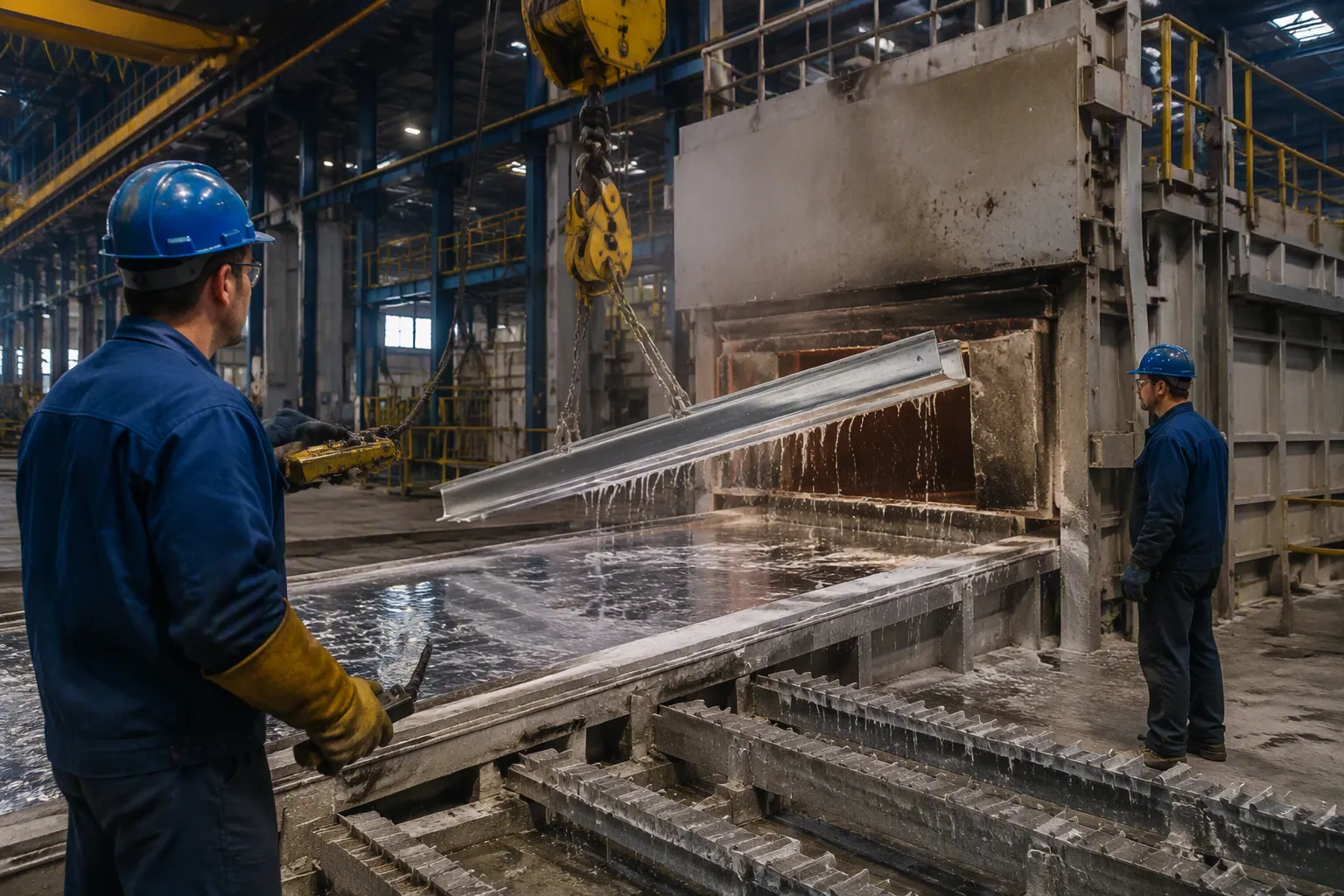
An Automatic Transfer Unit delivers repeatable results across every production run. The system moves each steel pipe through the same path at the same speed. You get uniform coating thickness because the withdrawal rate never changes. Manual operators cannot match this consistency. Their reaction times vary from load to load. The automated system removes that variability entirely.
Higher output follows naturally. The transfer unit never tires. It never takes breaks. The conveyor runs at a steady pace throughout the shift. Your furnace and bath stay busy instead of waiting for manual moves. You maximize production capacity without adding labor. Every hour of operation produces more salable product.
Energy Savings and Safer Operations
Energy efficiency improves because the system eliminates idle furnace time caused by manual delays. The furnace stays active and does not waste energy. Your fuel consumption drops and your energy bills follow.
Safety improves when you remove manual intervention. Operators no longer stand near open furnaces or molten zinc baths. The risk of burns and chemical exposure falls sharply. Consider what robotic automation achieves in these facilities:
Robotic automation removes workers from hazardous environments such as extreme heat and toxic acid vats. The fully automated layout prevents accidental chemical splashes, severe thermal burns, and chronic back injuries. Enclosed workstations establish a physical barrier that eliminates workplace injuries.
Your team works in a protected environment. They monitor screens instead of handling hot materials. This change reduces injury rates and improves morale. You also lower insurance premiums and workers’ compensation claims. The Automatic Transfer Unit pays for itself through these combined savings.
Implementing an Automatic Transfer Unit
Assessing Line Requirements
Start by evaluating your furnace, bath, and cooling stages. Walk through each transfer point on your line. Note where operators handle material manually. These manual points cause most errors in the process. Measure the distances between each stage. These measurements determine the conveyor length you need. Record your typical cycle times too. This data helps you match the system speed to your production pace.
Consider your material dimensions as well. Different pipe sizes require different roller spacing and conveyor widths. Measure your largest and smallest workpieces. Your system must accommodate both extremes. Examine your existing layout for space constraints. The conveyor needs a straight path between stages. You may need to relocate equipment to create that path. Identify bottlenecks in your current flow. A full on-site survey provides these answers for you.
Think about your future production goals too. Will your output volume increase next year? You want a solution that scales with your needs. Plan for expansion now rather than replacing equipment later.
Installation and Integration
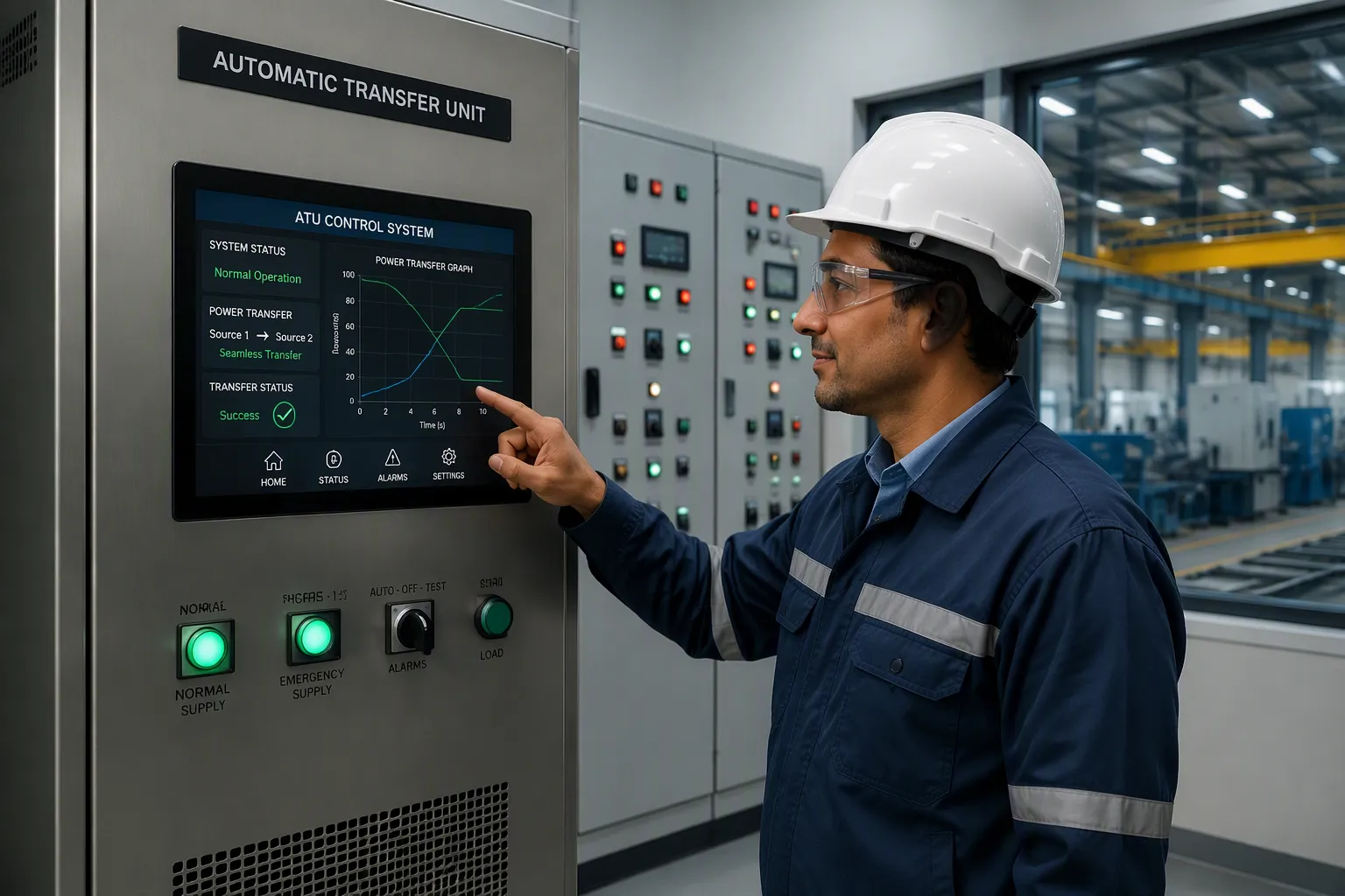
Select a unit with touch-screen operation controls. Look for connectivity options for computer or mobile management. These features make operation simple for your team. Operators monitor the system from a safe distance. They adjust settings with a few taps on the screen. This reduces training time and human error. The interface displays real-time data on speed, temperature, and position.
Integration with your existing furnaces, baths, and cooling equipment is straightforward. The installation team connects the conveyor system to your current controls. Piping and controls link both systems together. The integration creates a cohesive production line.
Your staff installs the conveyor system during a scheduled shutdown. This approach minimizes production loss. Technicians mount the conveyor belt, rollers, and sensors. They connect the control system to your plant network. Testing follows installation. You run sample materials through the system. You verify timing, positioning, and cooling performance. Operators receive training on the new controls. Your plant achieves higher efficiency with minimal downtime.
Best Practices for Long-Term Results
Maintenance and Monitoring
You protect your investment with a regular maintenance schedule. Inspect conveyor belts for wear and proper tension. Check rollers for smooth rotation. Clean sensors so they read positions accurately. The cylinder-based transfer mechanism needs attention too. Watch for these common signs of wear:
- · The cylinder drifts and cannot hold its position
- · Motion becomes jerky or uneven during the stroke
- · Oil leaks from seals, either internally or externally
- · The cylinder responds slowly or not at all to control signals
- · Abnormal noise occurs while the cylinder moves
Your control system generates valuable performance data. Use this data to catch deviations early. Real-time tracking and logging maintain a detailed record of all transfers. Automated alerts instantly flag failed or delayed transfers. Historical data analysis supports ongoing optimization. You review past transfer patterns and adjust settings for better performance. Centralized dashboards provide end-to-end visibility. They help you identify gaps in transfer processes over time.
Sensor data can also optimize your maintenance intervals. Continuous condition monitoring captures voltage fluctuations, temperature variations, vibration patterns, and response times. Machine learning models detect subtle degradation signatures before sensor malfunctions occur. This lets you schedule maintenance during planned downtime instead of emergency repairs. Organizations adopting these predictive maintenance strategies achieve reduced maintenance costs and improved system reliability.
Staff Training and Adoption
Your operators need proper training on the touch-screen controls. Show them how to adjust speed, monitor temperature, and verify positioning. Teach them to read the dashboard data. They should recognize normal operating parameters and spot deviations quickly. Mobile and computer management tools extend their reach. Operators can check system status from anywhere in the plant.
Training should cover emergency procedures too. Operators must know how to stop the Automatic Transfer Unit safely. They should understand what each alarm means and how to respond. Schedule refresher sessions regularly. New hires need the same thorough introduction. A well-trained team adopts the system faster. They trust the automation and use it effectively. This reduces errors and keeps your line running smoothly.
Manual transfer errors disappear when you automate movement between furnaces, baths, and cooling equipment. The Automatic Transfer Unit handles every transfer with consistent timing and precise positioning. You get uniform coating thickness across each production run. The transfer unit also prevents idle furnace time, reducing wasted energy and lowering fuel costs. Your operators also stay away from open furnaces and molten zinc baths. The result is a safer workplace with fewer injuries. Assess your galvanizing line today. Identify every manual transfer point on your floor. Then consider implementing this technology to reduce errors and improve performance.
FAQ
How does the transfer unit handle different pipe sizes?
The system uses adjustable roller spacing and conveyor widths. You configure these settings through the touch-screen interface. The control system stores parameters for each product type. Switching between sizes takes minimal time. This flexibility lets you process various workpieces on the same line.
Can I integrate this unit with my existing furnace and bath equipment?
Yes. The transfer unit connects to your current heating furnaces, galvanizing baths, and cooling equipment. Your installation team links the conveyor system to existing controls. The unit integrates with your existing controls. This creates a unified production line without replacing your core equipment.
What maintenance tasks keep the system running reliably?
Inspect conveyor belts for wear and proper tension. Check rollers for smooth rotation. Clean sensors regularly so they read positions accurately. Watch the cylinder-based transfer mechanism for drift, jerky motion, or oil leaks. Your control system data helps you schedule maintenance during planned downtime.
How long does installation typically take?
Installation happens during a scheduled shutdown to minimize production loss. Technicians mount the conveyor belt, rollers, and sensors. They connect the control system to your plant network. Testing and operator training follow. Your specific timeline depends on line layout and integration complexity.
What training do operators need for the touch-screen controls?
Operators learn to adjust speed, monitor temperature, and verify positioning through the touch-screen interface. Training covers dashboard data reading and alarm response. Mobile and computer management tools extend their reach. Refresher sessions keep skills sharp. A well-trained team adopts the system faster and reduces errors.
Post time: Sep-21-2026