
Fluxing tank reprocessing cuts zinc consumption by removing dissolved iron from the flux bath before it reaches the galvanizing bath. That iron would otherwise react with zinc and form dross. One plant installed continuous flux regeneration and cut zinc consumption by 10–20% within a quarter (illustrative figure). You gain lower zinc costs, less dross and ash, consistent coating quality, and easier environmental compliance. How exactly do you apply fluxing tank reprocessing in your plant?
Key Takeaways
- · Iron in your flux bath creates dross and wastes zinc.
- · Fluxing tank reprocessing removes iron and cuts zinc use by 10–20%.
- · Audit your zinc losses first to find where zinc disappears.
- · Implement flux regeneration with automatic dosing and filtration.
- · Monitor chemistry and train operators to sustain lower zinc use.
Why Fluxing Tank Reprocessing Cuts Zinc Consumption
The Iron-Dross Link in Your Flux Bath
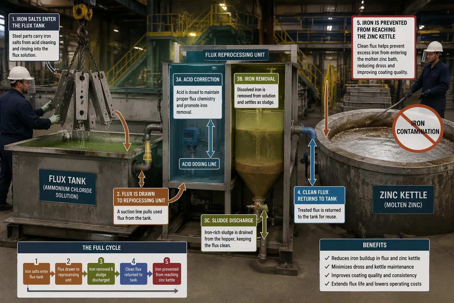
Your flux bath does not stay clean on its own. Acid cleaning removes iron from steel surfaces as dissolved salts. When rinsing after acid cleaning is incomplete, those iron salts travel into the flux tank. The flux layer, typically a wet ammonium chloride solution used in wet-flux or dry-flux processes, accumulates iron when you do not monitor and adjust its chemistry consistently. That iron then moves into the zinc kettle.
Molten zinc holds very little iron. At a typical galvanizing temperature of 850°F (454°C), the solubility limit for iron in molten zinc is only 0.035 percent—roughly 35 iron atoms per 100,000 zinc atoms. Any iron concentration above that threshold precipitates out and begins to react metallurgically with the surrounding zinc, building up the dross that accumulates in the kettle.
At a typical galvanizing temperature of 850°F (454°C), the solubility limit for iron in molten zinc is only 0.035 percent—roughly 35 iron atoms per 100,000 zinc atoms. Any iron concentration above that threshold precipitates out and begins to react metallurgically with the surrounding zinc, building up the dross that accumulates in the kettle.
That dross consumes zinc directly. Every pound of iron that enters the kettle ties up zinc in zinc-iron alloy crystals. You pay for that zinc, and you lose it as waste. The largest source of this free iron is iron salts carried into the flux tank and then into the zinc kettle from the acid cleaning stage, particularly when rinsing is incomplete.
What a Regenerated Flux Bath Saves You
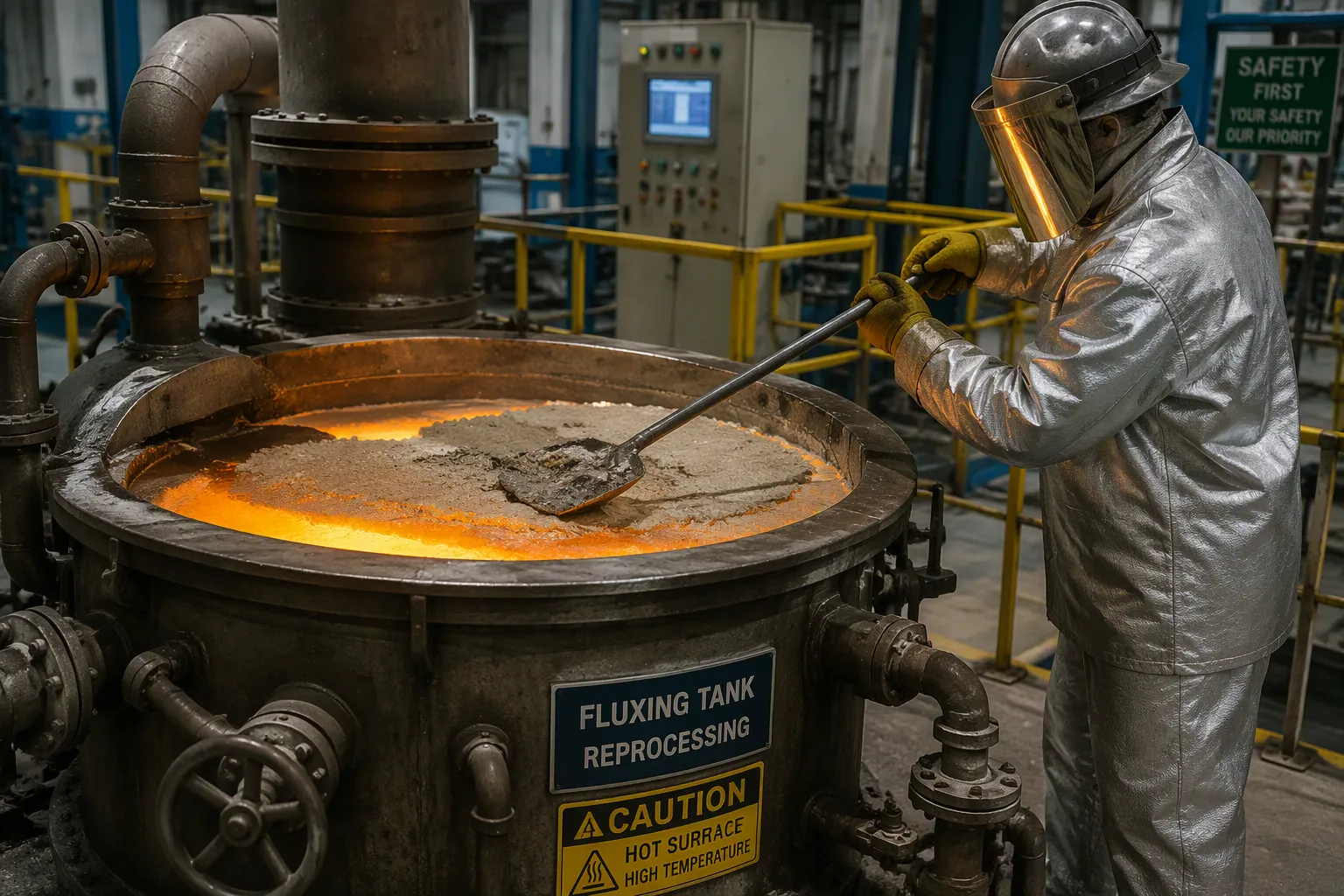
Fluxing tank reprocessing breaks the iron-dross link through continuous regeneration. The system uses two combined chemical reactions: an acid-base reaction and an oxide reduction. Together, these reactions correct flux acidity and cause dissolved iron to precipitate as sludge. The sludge collects at the bottom of the tank, where you tap it regularly. A separate filter press then extracts oxidized iron in-line.
| Reaction / condition | Role in iron hydroxide sludge formation during regeneration |
| Fe³⁺ + 3H₂O → Fe(OH)₃ + 3H⁺ | Ferric iron hydrolyzes to insoluble ferric hydroxide when excess acid is absent. |
| Fe²⁺ → Fe³⁺ + e⁻, then Fe³⁺ hydrolysis | Dissolved ferrous iron is oxidized to ferric iron and then hydrolyzed to Fe(OH)₃ sludge. |
| 4Fe(OH)₂ + 4OH⁻ + 6H₂O + O₂ → 4Fe(OH)₃ + 4H₂O | Aeration oxidizes ferrous hydroxide to ferric hydroxide, which precipitates and can be removed by settling. |
| Fe²⁺ + 2H₂O → Fe(OH)₂ + 2H⁺ | A local rise in pH from consumption of H⁺ can precipitate ferrous hydroxide, another form of iron hydroxide sludge. |
The filter press design ensures that essential ammonium and zinc chlorides stay in the flux solution. You keep your flux composition balanced and under control. The system converts Fe2+ into Fe3+ to form sludge, continuously treats the flux in a closed cycle, and monitors key process parameters.
The savings add up quickly. One plant cut zinc consumption by 10–20% within a quarter after installing continuous flux regeneration (illustrative figure). You also reduce ash and dross generation, lower flux consumption, and prevent black spots and zinc ash residues on galvanized parts. Your coating quality stays consistent, and your environmental compliance gets easier.
Audit Your Current Zinc Losses First
Measure Zinc Loss by Process Point
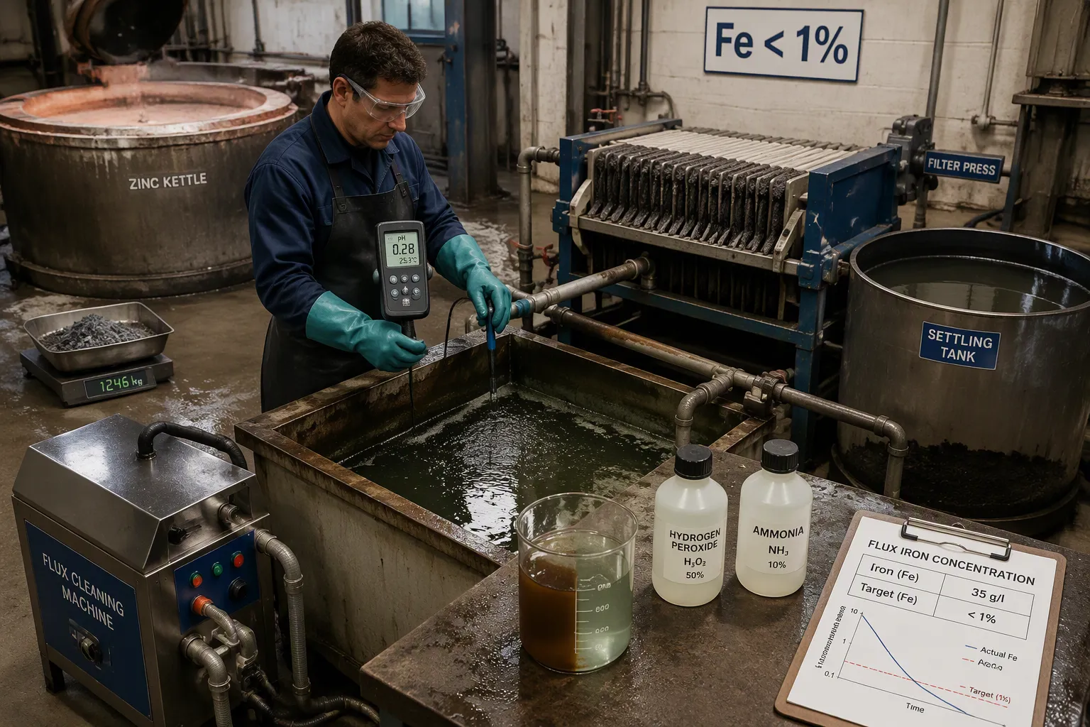
You cannot fix a loss you never measure. Most galvanizing plants rarely measure zinc use directly. They track total galvanized product weight and base financial charges on that weight. Zinc usage gets estimated only over longer periods, such as monthly or yearly, rather than at individual process points. That habit hides where your zinc actually goes.
Start with a weekly zinc usage audit. Flag any usage spike right away. Then monitor bath parameters continuously to keep the process within specification. Check zinc and alloy levels regularly to hold bath composition steady and control excessive dross formation.
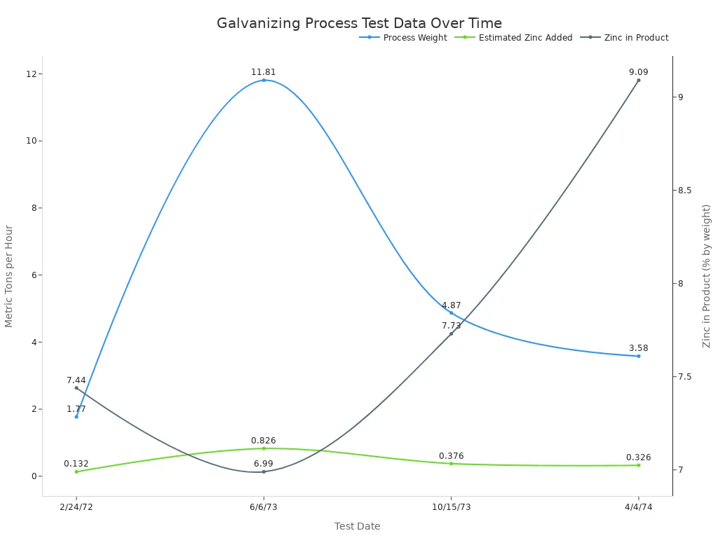
Ash and dross together should stay under 20 percent of zinc consumption. Values above that level may point to flux-dryer or pickling problems. One older benchmark treats ash above 13 percent of zinc consumed as excessive, and dross above 10 percent as excessive. More recent benchmarks relate ash and dross to product galvanized instead: ash above 0.8 percent of production is excessive without an ash box, above 0.4 percent with a manual ash box, and above 0.2 percent with a motorized ash box. Dross above 0.6 percent of production is considered excessive.
Check Flux Chemistry and Equipment Readiness
Now compare your bath readings against target ranges. The table below shows what to watch and when to act.
| Audited Parameter | Target Range | Drift Consequence | Alert Trigger |
| Bath Temperature | 455–460°C | Dross type shift, viscosity change | ±2°C from setpoint |
| Aluminum Content | 0.18–0.22% (GI) / 0.12–0.135% (GA) | Inhibition layer failure / powdering | ±0.01% Al trend |
| Iron Saturation | <0.03% Fe | Accelerated dross generation | Fe approaching 0.025% |
| Zinc Ingot Addition Rate | Per line-speed model | Bath level deviation, coating weight shift | Addition vs. consumption variance >5% |
| Dross Generation Index | <0.8 kg/coil (GI) / <1.1 kg/coil (GA) | Roll marking, surface defects | Exceeds trend baseline by 20% |
Traditional auditing relies on shift-end lab sample review, monthly inventory reconciliation, and reactive review after defects appear. Advanced methods catch drift within 10 minutes using real-time aluminum and iron trend alerts, track per-coil zinc consumption against target, and predict dross generation with trend-baseline alerts. Closed-loop coating correction can respond under 8 seconds instead of the roughly 30-second lag from operator XRF feedback.
Implement Fluxing Tank Reprocessing Step by Step
Optimize Flux Parameters and Reagent Dosing
You start by measuring what you have. Determine the dissolved Fe2+ concentration in your flux, expressed as grams per liter or percent, and measure the volume of flux solution you plan to treat. Then identify the concentrations of your treatment chemicals, mainly hydrogen peroxide and ammonium hydroxide. Use the stoichiometry of the oxidation and precipitation reaction to calculate the required doses from the Fe2+ concentration and solution volume. This calculation keeps your reagent use precise instead of guesswork.
The treatment window matters. Adjust the pH to about 4.2, keep the flux hot near 70 °C, add diluted hydrogen peroxide, and aerate for several hours. Let the Fe(OH)3 settle before you decant and remove the sludge. These conditions drive the conversion of dissolved Fe2+ into Fe3+ sludge, which is the form your filter press can capture.
A PLC-controlled system handles this dosing automatically. The control layer regulates the start-stop duration and frequency of acid and alkali dosing pumps based on an optimal pH adjustment value. ORP sensors feed data to the PLC for real-time control and alarm monitoring through SCADA. When effluent concentration exceeds the target value, the AI algorithm adjusts the next precipitant dose using a proportional coefficient optimized through a PID control algorithm, with a proportional band of 0.1–0.5 and an integral time of 30–60 seconds. A mixer dissolves each reagent thoroughly before it enters the bath.
Automate Filtration and Sludge Removal
Once dosing is stable, you close the loop. The system continuously circulates flux from the fluxing tank through the treatment system in a closed cycle. PLC-controlled automatic dosing adds reagents that convert dissolved Fe2+ into Fe3+ sludge while maintaining flux pH. pH and ORP probes with transmitters monitor and regulate the process. The treated flux then passes through a filter press that removes oxidized iron sludge.
The filter press design is the critical detail. It removes oxidized iron without removing ammonium chloride or zinc chloride. Your flux composition stays balanced and under control, so you do not strip out the chlorides your process depends on. Clean, chemically balanced flux returns to the fluxing tank.
This closed-cycle approach makes fluxing tank reprocessing easy to operate. The PLC has built-in preset control logic based on parameter thresholds, such as the pH adjustment range and reagent addition concentration. When real-time parameters exceed limits, the system generates control commands that drive the actuators, including acid, alkali, and flocculant dosing pumps. SCADA displays sensor data, actuator status, and module operating parameters through a human-machine interface, and it triggers alarms when monitored parameters exceed preset alarm thresholds. New or inexperienced operators can manage the routine because the system handles the dosing decisions and filtration cycle automatically.
Avoid Common Fluxing Mistakes That Waste Zinc
Control Iron Contamination and Sludge Build-Up
Iron contamination is the most expensive mistake in your flux tank. High iron content in the flux—sometimes as high as 4%—deposits on steel and enters the zinc kettle, where it reacts with zinc to form dross. One expert notes that iron in flux “reacts with zinc to form dross,” and that high Fe at 35 g/l “will be costing a lot of zinc in the form of both splash (ash created, by poor drying) and by dross production.” A reasonable target is to never let Fe exceed 1%. Without proper cleaning, Fe can reach 35 g/l, causing significant zinc loss.
Several common errors drive this contamination:
- · Low pH from acid carryover: A flux tank pH below 1 indicates contamination by pickle acid. This dilution reduces ammonium chloride and zinc chloride concentrations, and the acid carryover introduces iron that leads to dross. A brown-to-green color change confirms acid contamination.
- · Improper iron removal: Attempting to remove iron with air bubbling alone or with ineffective proprietary brews is a mistake. Proper removal requires making iron insoluble through oxidation with hydrogen peroxide, adjusting pH with ammonia, and filtering or settling the iron hydroxide.
- · Inadequate flux cleaning: Not using a proper flux cleaning machine allows iron and impurities to accumulate.
- · The misconception that iron in flux is harmless: Some operators believe iron in triple salt flux has no adverse effect, but expert opinion contradicts this. Relying on this misconception leads to failure to control iron, increasing dross and zinc consumption.
Remember the ratio: 1 gram of iron produces approximately 25 grams of dross. Dross itself is 96% zinc and 4% iron. Every gram of iron you fail to remove costs you 25 grams of dross—and most of that is zinc you paid for.
Keep Flux Chemistry Balanced Under Load
High production throughput stresses your flux chemistry. You must adjust the flux pH regularly, approximately once every two days, to maintain the correct range. Use a continuous filter press to remove iron(III) hydroxide from the flux, preventing iron buildup that can affect performance. Employ two flux tanks in turns to allow for continuous operation while one tank is being maintained or adjusted. Control the ammonium chloride concentration to provide adequate buffering capacity, which helps stabilize pH. Perform acid demand tests to determine the correct amount of HCl needed to lower pH to the desired level, such as 4.2, and avoid excessive additions. Avoid excessively low pH, as it increases corrosiveness and can raise Fe2+ levels faster, requiring more frequent cleaning.
The ammonium chloride to zinc chloride ratio should stay between 2:1 and 3:1. If the ratio moves toward 1:1, more black deposit forms on the kettle. Black deposits on galvanized parts are flux residues that you can wash off with water; their presence indicates poor skimming practice.
Adding ammonium hydroxide to neutralize excess acid in flux is equivalent to adding ammonium chloride. Each U.S. gallon of ammonium hydroxide equals 11 pounds of ammonium chloride. This means severe acid carry-over—often from a missing or stagnant rinse—can silently raise your ACN. One plant reported ACN rising from 0.8 to 1 over 4 months with double salt at 45 °C. Monitor your ACN target of 1.6 and your pH range of 4–4.5 to catch this drift early.
Track Results and Sustain Lower Zinc Use
Monitor Bath Chemistry and Zinc Consumption
You need clear numbers to know whether the system works. Track flux iron content every week. Keep it below 1 percent. Record pH daily. Hold it between 4 and 4.5. Keep the ammonium chloride to zinc chloride ratio between 2:1 and 3:1. Monitor the ACN target near 1.6.
Track zinc usage against production. Weigh ingots added to the kettle. Compare that weight against galvanized product tonnage each month. Ash and dross together should stay under 20 percent of zinc consumption. A higher number means iron still enters the kettle.
pH and ORP probes give you real-time data. They feed the PLC controller. The controller adjusts reagent dosing automatically. Your job is review. Check the SCADA screen each shift. Look at trend lines for Fe, pH, and ORP. Investigate any drift before it becomes a problem.
Train Operators on the Reprocessing Routine
Operators do not need a chemistry degree. The PLC handles dosing decisions. They still need training to keep the system running well.
Teach them the basic cause-and-effect. Dissolved iron in the flux bath costs zinc. Fluxing tank reprocessing removes that iron as sludge. The filter press captures the sludge. The operator monitors the press and schedules the sludge tap.
Train them on the SCADA interface. Show them where to find pH and ORP readings. Explain each alarm threshold and the correct response. Practice the reagent refill procedure. The dosing pumps consume hydrogen peroxide and ammonium hydroxide. Low reagent levels stop the treatment process.
Set a daily checklist. Check the filter press for proper cake formation. Confirm the mixer is running. Verify pump pressures. Review the shift log. Monthly, compare zinc consumption against the target you set in the audit. Adjust the dosing calibration when you see drift.
The system is easy to operate, but it is not self-maintaining. A short training session each month keeps new operators sharp. Consistent monitoring and routine care sustain lower zinc use year after year.
Dissolved iron in your flux bath creates dross and drives up zinc consumption. Fluxing tank reprocessing removes that iron through continuous regeneration, so you waste less zinc. You gain lower zinc and flux costs, less ash and dross, better coating quality, and stronger environmental compliance.
Every pound of iron you remove from the flux bath protects zinc in the kettle and keeps your coating consistent. Take action now. Begin with a zinc-loss audit. Set a reduction target. Implement flux regeneration and filtration. Then track monthly results against that target. These practical steps convert iron control into measurable savings for your galvanizing line.
FAQ
How does the regeneration process reduce zinc consumption?
Fluxing tank reprocessing removes dissolved iron from your flux bath before it reaches the zinc kettle. There, the iron would react with zinc to form dross. Removing the iron as sludge cuts dross formation. You waste less zinc and your consumption drops.
What savings can you expect?
One plant cut zinc consumption by 10–20% within a quarter after installing continuous flux regeneration. Treat that figure as illustrative, not a guarantee. You also lower ash and dross generation. Flux consumption decreases. Coating quality remains consistent.
Does the system remove flux chemicals?
No. The filter press removes oxidized iron sludge only. It leaves ammonium chloride and zinc chloride in solution. Your flux composition stays balanced and under control. You maintain the chemistry your process needs.
Is the system hard to operate?
Not difficult. PLC controls handle dosing and filtration automatically. pH and ORP probes supply real-time data. Operators watch the SCADA screen and refill reagents. New or inexperienced operators can run the routine confidently.
Post time: Oct-14-2026